General Information
Max output of line: max. 2000kg/h @ 4h 0,55kg/dm³, depending on reaction time (line efficiency 92.5 %)
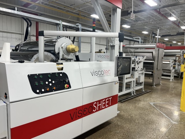
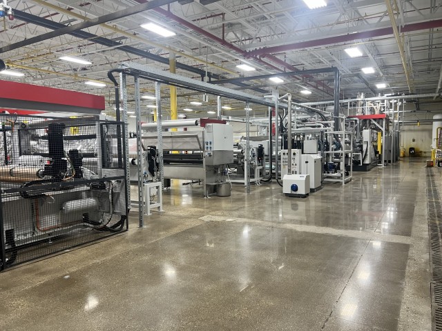
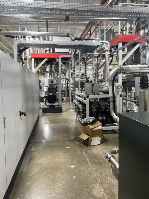
viscoSHEET 2000S165C – ground floor extrusion line
The final sheet has the following specifications:
Final sheet width: 518 – 800 mm Final sheet thickness: 860 µm
Outputs:
Max. output main-extruder: 1600 kg/h (with 100% warm feed material) Max output co-extruder: 400 kg/h
Item 1. Material Handling
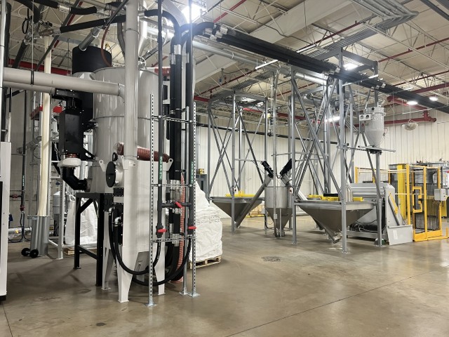
Item 1.1 Big Bag Mixing Station for 3 Materials
- Volume per hopper: approx. 1000 l
- Number of hoppers: 4 (3 including crane)
- length of vacuum transport pipe: 18 m + 4 x 90 ° elbow pipes r 500
The Big Bags are discharged over the hopper Via a feeding screw conveyed into a mixing hopper. The formulation can be adjusted via a control unit.
By vacuum transport the flakes are transferred from the mixing hopper to the next process step.
Item 1.2. Material handling and transport to Crystallizer (before SSP)
The material is transported from the Big Bag mixing station via a vacuum feeding system to the crystallizer (CRY).
The vacuum feeding system consists of a vacuum pump, material receiver, level sensor and installation material. Max. possible feeding distance 18 m (59 ft).
Technical data and components
- Double stage side channel blower:
-
- 11 kW (max. suction tube length 15 m (50 ft) horizontal, 6 m (20 ft) vertical, max. 3 x 90°)
- Dimensions: 600x820x2100 mm (2×2.7×6.9 ft)
- Assembling material for vac. feeding:
-
- Rigid piping Ø 76 mm (Ø 3 inch)
- Pipework for vacuum supply to the receiver (aluminium pipe: 2×6 m (2×20 ft) + 6×90° elbow pipe)
- For material transportation (stainless steel pipe: 3×6 m (3×20 ft) + 8×90° elbow pipe)
- Material receiver:
-
- 100 l volume and pneumatic controlled outlet valve
Item 2. viscotec pre-treatment
Item 2.1. Crystallizer (cry 40 before SSP)
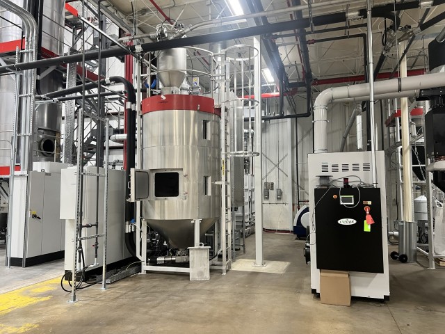
The viscotec crystallizer cry 40 performs a two-stage process on PET material. (1) Amorphous material is crystallized by passing the glass transition state and (2) the surface moisture (main moisture content) is removed. The material is pre-heated to the dedicated process temperature. The process is based on hot-air circulation inside the material vessel, the hot-air flow can be used in an open or closed loop design. The integrated agitator + fixed mounted breaker bars inside the material vessel avoid clumps of agglomerated materials. The air-circulation technology adds a super-efficient de-dusting step to the material.
Technical data and components
- Volume of crystallizer tank: 4000 l
- Installed power: 280-330 kVA
- Heating power: 180 kW
- Side channel blower: 4 x 18,5 kW incl. pressure relief valve
- Moisture level: < 500 ppm
- Dust separation unit Incl.
- Suction box: 3xØ 76 mm (3xØ 3 inch) material pipe connection and 1xØ76 mm (1xØ 3 inch) for conveying air
- Dimensions: 6100 x 3700 x 5200
- Condensate separator: CDF 4000
Item 2.2. Material handling and transport from CRY to viscoSTAR
The material (flake or pellets) is transported via vacuum feeding system to the viscoSTAR preheater. Max. possible feeding distance 30 m (100 ft).
Technical data and components
- Feeding accessories kit: 3x conveying valve
- Double stage side channel blower: 20 kW incl. cooling device (max. suction tube length 25 m (82 ft)) horizontal, 6 m (20 ft) vertical, max. 3 x 90°)
- Dimensions:2800x2100x2300 (9.2×6.9x6x7.5 ft)
- Assembling material for vac. feeding:
-
- Rigid piping Ø 76 mm (Ø 3 inch)
- Pipework for vacuum supply to the receiver (aluminium pipe: 4×6 m (2×20 ft) + 8×90° elbow pipe)
- For material transportation (stainless steel pipe: 9×6 m (9×20 ft) + 12×90° elbow pipe)
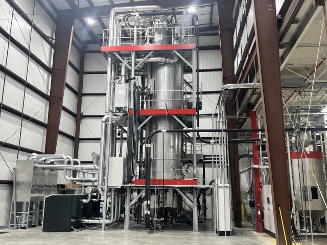
Item 3. viscotec dynavac treatment Item 3.1. viscoSTAR 150 S4.0
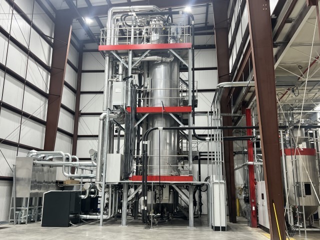
The prepared material is transported via vacuum feeding system to the preheater at the top of the reactor by batches. The flakes or pellets are treated with the viscotec preheating technology to a temperature of min. 160°C up to max. 220°C., set under vacuum, and then loaded to the reactor vacuum vessel. Inside the reactor vessel the reaction takes place and the intrinsic viscosity of the material is increased as a function of material type and shape, adjusted residence time, and material temperature.
After the elapsed reaction time, batches of approx. 100 kg (220 lb) flakes, or 200 kg (440 lb) pellets are discharged under vacuum with a special designed outlet device to prevent mixing of the material and to guarantee a first in first out process. In the outlet chamber the flakes or pellets are brought back to atmospheric pressure again and are ready for the next process step. Technical Data and Components
- of Preheaters: 3
- of discharge vessel: 2
- Installed heating power reactor: 16 x 6 kW (reactor wall)
- Installed heating power preheater: 120 kW
- Installed power KAESER air blower: 3 x 55 kW
- Vacuum pumps reactor vessel: Multi-stage vacuum system 1000 m³/h (35300 ft³/h)
- Vacuum pump preheater/outlet: Rotary vane pump 300 m³/h (10600 ft³/h)
- Condensation vessel: Counter current system with rinsing fluid
- viscoSTAR dimensions: 4000x4000x13100 mm (13.1×13.1×43 ft)
- Net volume of reactor: 14200 l
- output: approx. 2000kg/h @ 4h 0,55kg/dm³ depending on reaction time
- IV increase:
-
- average 0,01 – 0,02 dl/g/h (pellets)
- average 0,02 – 0,04 dl/g/h (flakes)
- depending on starting iV, chemical composition, and contamination
- Dust cyclone: 3 x 960x960x2600 mm (3.1×3.1×8.5 ft)
Enlarged maintenance platform:
Instead of the conventional reactor platforms which are connected with a vertical ladder, this steel construction with stairways to the several enlarged maintenance platforms ensures a safer and much easier access to the service and cleaning points.
Especially when using multiple reactor units, the base frame can be extended to tie all platforms together and to build one large gantry.
The complete line is fully electrical equipped and controlled via a B&R PLC with decentral IO´s. The operator interface is a touch screen featuring real time trending, fault display and recipe management. The PLC has to be connected to an accessible I-net-router with a physical IP address for online maintenance and diagnostic.
Technical data and components
- Supply: 400-480V, 50/60 Hz
- PLC and terminal brand: Bernecker & Rainer, Power Panel PP420
Heat recovery system for energy savings :
The exhaust air from the preheaters is used to heat up the air from the Kaeser blowers before entering the heating battery. A tube bundle heat exchanger is used for this and the saving is approx. 30 kW per preheater.
Item 3.2. Nitrogen generator unit
The nitrogen is used as a transport gas to remove the volatiles faster from the reactor vessel and to reduce the remaining oxygen level in order to prevent a discoloration of the material.
The technology is based on the absorption principle with a carbon molecular sieve. The absorption procedure separates the nitrogen molecules from the oxygen molecules. This ensures a continual production of the desired nitrogen purity.
Technical Data and Components
- Nitrogen generation system
-
- Capacity:
- 2,7 Nm³/h at 99,999 % purity
- 4.7 Nm³/h at 99,99% purity
- Max. purity:
- 99,999 % nitrogen (at low capacity)
- Nitrogen tank: 150 l
- Capacity:
Item 3.3. Material handling and transport – from viscoSTAR to FG buffer and NFG bagging station
The perfect dried and decontaminated material is transported via a vacuum feeding system from the viscoSTAR outlet vessel (MTO) to the FG buffer silo or NFG bagging station.
The vacuum feeding system consists of a vacuum pump, material receiver, and piping material. Max. feeding distance 18m (59 ft).
Technical Data and Components
- Double stage side channel blower:
-
- 11 kW incl. cooling device (max. suction tube length 15m (50ft) horizontal, 6m (20ft) vertical, max. 3 x 90°)
- Dimensions: 850x820x2100 mm (2.8×2.8×6.9 ft)
- Assembling material for vac. feeding:
-
- Rigid piping Ø 76 mm (Ø 3 inch)
- Pipework for vacuum supply to the receiver (aluminium pipe: 6×6 m (6×20 ft) + 12×90° elbow pipe)
- For material transportation (stainless steel pipe: 6×6 m (3×20 ft) + 8×90° elbow pipe)
- Material receiver 2x 200 l volume, with pneumatic controlled butterfly valve
Item 4. Material storage and bagging
Item 4.1. 2x inline buffer silo 1500 l
The finished material can be transported to the viscoSHEET line or via air blowing system to the big bag filling station.
Technical data:
- Silo: 1500 l insulated stainless steel vessel
- Suction box: 3x Ø 76 mm (3x Ø 3 inch) material pipe connection and 1xØ 76 mm (1xØ 3 inch) for conveying air
- Maintenance platform: Access ladder, stair head and handrail
Item 4.2. 2x Material handling and transport from inline buffer silo 1500 l to viscoSHEET
The material is transported via vacuum feeding system (viscoSHEET central vacuum station) to the gravimetric dosing system of the viscoSHEET line.
Max. possible feeding distance 18 m (59 ft). Technical data:
- Feeding accessories kit: 1x conveying valve
- Assembling material for vac. Feeding: For material transportation (stainless steel pipe: 3×6 m (3×20 ft) + 4×90° elbow pipe)
Item 4.3. 2x Material handling and transport via Air blowing system to Big Bag filling station
The material is transported via an air conveying system from the inline buffer silo to the storage silo in order to achieve a further material cooling.
The air conveying system consists out of an air blower, material receiver, rotary valve and material pipework.
Technical data:
- Air blower: 4 kW
- Assembling material for air feeding: Rigid piping Dm. 160 mm for pipework
- Rotary valve: 0,55 kW frequency controlled
- Material receiver: buffer vessel above rotary valve
- Heat exchanger: In order to cool the conveying air
Item 4.4. 2x Storage silo 1200 l incl. Big Bag filling station for pneumatic transport
The finished material can be stored inside the 1200 l silo to be filled afterwards in super sacks. Technical data:
- Silo: 1200 L insulated stainless steel vessel
- Big Bag filling device: 1900 x 1900 x 7000mm (6.3 x 6.3 x 23 ft)
Item 5. Extrusion Part – dosing unit (ground floor extrusion) Item 5.1. Suction and gravimetric dosing unit for extrusion part
The raw material is transported to the gravimetric dosing unit above the extruder, where each component is individually weighed before being fed into the extruder intake zone. The material feeding is done with the central vacuum station incl. dust filter.
Technical Data and Components Main-extruder dosing unit
- Number of main components: 3 (100 l each)
- Number of additives: 2 (10 l each)
- Edge trim recirculation: Incl. Co-extruder dosing unit
- Number of main components: 2 (100 l each)
- Number of additives: 2 (10 l each) Central vacuum station: 1100 m³/h, 22 kW
Not included in the price are the storage bins or silos for the components as well as the piping for additive components.
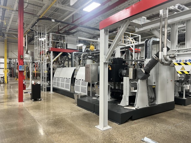
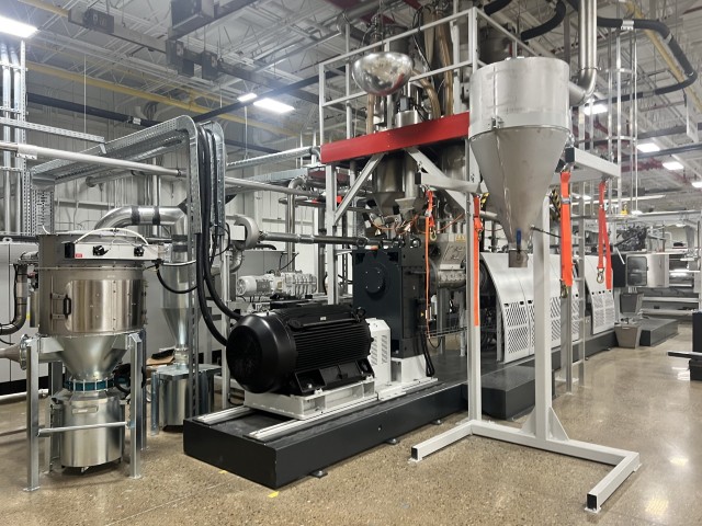
Item 5.2. Main extruder (single screw 165)
The Starlinger single screw extruder is a state-of-the-art technology which captivates by its robustness, the special screw design for rPET flake materials, and the flexibility to process different products for highest quality standards.
Features:
- Gentle material treatment
- Highest flexibility and adaptability to different material and the changing requirement of
- rPET processors
- High automation and user-friendliness leads to highest efficiency Technical Data and Components
- Extruder screw: Ø 165 mm (6.5 inch) Nitride-hardened and armor-plated
- Extruder length: 24 L/D
- Main drive power: 295 kW AC, direct drive, frequency controlled,
- Barrel and cooling: Bimetallic design, air cooling fans
- Melt pressure display and alarm: Yes
- Extruder extension for venting: 16 L/D
Gaseous impurities are removed and evacuated with high vacuum technology from the melt by using the extruder extension with two degassing openings.
The vacuum unit consists of condensate-separating containers, mechanical filtration and two rotary vane vacuum pumps and one roots pump.
Vacuum operation range: <10 mbar
Item 5.3. Screen changer V-Type 250 Filtration
The heated body is equipped with two filter pistons. Each bolt has one screen cluster. The melt is split into two channels and after passing the filtration the two channels are merged again.
Screen change:
During a screen change one of the screen cavities (25%) is removed from the process, allowing for three of the screen cavities (75%) to remain in operation.
Automatic back flush:
If the pressure- difference increases up to a defined set point, the pistons are moving into the back flush position. The direction of the melt will be changed, so the contaminations on the screens will be pressed out through the drain channel. The back flush cycles have no influence on quality and process and is done with power backflush technology
3 screen cavities are in the process (75%)
Consisting of:
- Number of screens: 4
- Screen area: 4 x 415 cm^2
- Continuous operation: Yes
- Hydraulic unit
Item 5.4. Melt pump
The electrical heated gear pump increases the melt pressure and keeps it constant to avoid pressure and output fluctuations.
Heated adapters on both sides of the pump, equipped with low maintenance AC drive, gear box and cardan shaft, melt pressure sensors at pump inlet and outlet incl. melt pump control system.
Technical Data and Components
- Heating power: 12 kW
- Conveying volume of pump: 350 cm³/rev. (21,36 inch³/rev.)
- output: 1800 kg/h (3965 lb/h)
- Motor power rating: 19,4 kW
Item 5.5. Co-extruder (single screw 85)
The Starlinger single screw extruder is a state-of-the-art technology which captivates by its robustness, the special screw design for rPET flake materials, and the flexibility to process different products for highest quality standards.
Features:
- Gentle material treatment
- Highest flexibility and adaptability to different material and the changing requirement of rPET processors
- High automation and user-friendliness leads to highest efficiency
Technical Data and Components
- Extruder screw Ø: 85 mm (3.35 inch) Nitride-hardened and armor-plated
- Extruder length: 24 L/D
- Main drive power: 97 kW AC, direct drive, frequency controlled
- Barrel cooling: Bimetallic design, air cooling fans
- Melt pressure display and alarm: Yes
- 3-Layer feed block:
-
- Fixed geometry with two cartridge heaters; adjustable with exchangeable inserts
- Layer distribution: 10 – 80 – 10
- ABA, ABB, BBB inserts included
- Extruder extension for venting: 16 L/D
Gaseous impurities are removed and evacuated with high vacuum technology from the melt by using the extruder extension with two degassing openings.
The vacuum unit consists of condensate-separating containers, mechanical filtration and one rotary vane vacuum pump.
Vacuum operation range: < 10 mbar
Item 5.6 Screen changer K-SWE-125 4K RS
Filtration:
The heated body is equipped with two filter pistons. Each bolt has one screen cluster. The melt is split into two channels and after passing the filtration the two channels are merged again.
Screen change:
During a screen change two of the screen cavities (50%) are removed from the process, allowing the other two screen cavities (50%) to remain in operation.
Automatic back flush:
If the pressure- difference increases up to a defined set point, the pistons are moving into the back flush position. The direction of the melt will be changed, so the contaminations on the screens will be pressed out through the drain channel. The back flush cycles have no influence on quality and process.
3 screen cavities are in the process (75%)
Technical Data and Components
- Number of screens: 4
- Screen area: 4x 122 cm² (4x 18.9 inch²)
- Continuous operation: Yes
- Hydraulic unit: 3,45 kW
Item 5.7. Melt pump for co-extruder
The electrical heated gear pump increases the melt pressure and keeps it constant to avoid pressure and output fluctuations.
Heated adapters on both sides of the pump, equipped with low maintenance AC drive, gear box and cardan shaft, melt pressure sensors at pump inlet and outlet incl. melt pump control system.
Technical Data and Components
- Heating power: 3.2 kW
- Conveying volume of pump: 90 cm³/rev. (5.49 inch³/rev.)
- output: 400 kg/h (2200 lb/h)
- Motor power rating: 5.4 kW
Item 5.8. Extrusion die 2000 mm (79 inch)
Manual adjustment
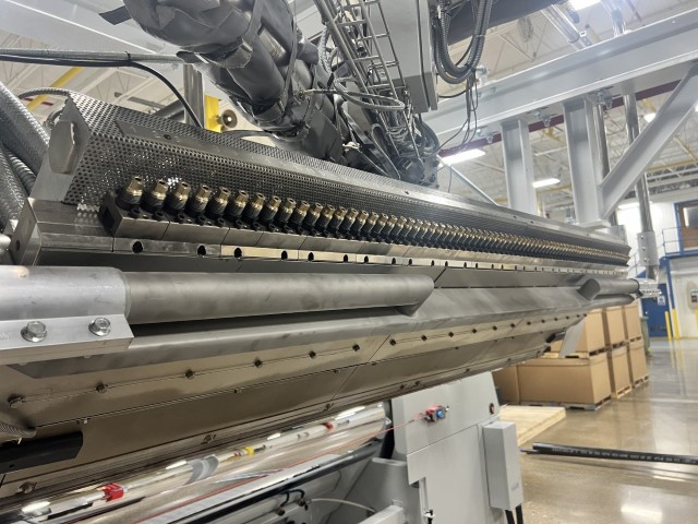
Complete with co-extrusion connector; die insulation consists of a ceramic fiber and stainless steel cover, electrical equipment, and internal control thermocouples. Die lip heaters for PET film and PET multi layer structures, lip heaters installed on both sides of die lip area, including electrical equipment. Set fixed external deckles for the flat die 300 mm on each side.
Equipped with gear racks for easy splitting of the die without dismounting.
auto DIE
According to the set point of the thickness control system, the automatic regulation sets up the thickness profile within the tolerance set point. The operator can change the thickness very easily on the control panel and the system is adjusting it automatically.
Item 5.9. Electrical equipment and controls
The complete line is fully electrically equipped and controlled via a B&R PLC with decentral IO´s. The operator interface is a touch screen featuring real time trending, fault display, and recipe management. The PLC has to be connected to an accessible I-net-router with a physical IP address for online maintenance and diagnostics.
Technical Data and Components
- Supply: 400-480 V, 50/60 Hz
- PLC and terminal brand: Bernecker & Rainer, automation Panel 19”
Item 6. Downstream Equipment
Item 6.1. Roll stack 2000 mm (78.7 inch) width
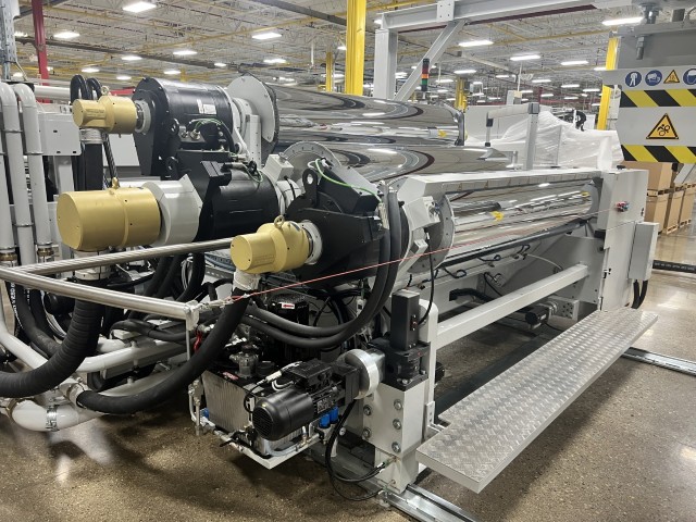
Horizontal roll stack 2000 mm (78.7 inch) in width, with very efficient cooling due declining cooling channels, and a higher positioned chill roll (C2) resulting in greater surface contact > 420°. Direct torque-driven chill rolls ensuring long term quick response with no maintenance.
The positioning of the roll stack is done with servo controlled spindle-drives which guarantees a 100% reproducible process. The roll-gap adjustment between C0 and C1 will be done automatically in the program. The chill rolls are made out of forged heat-treatable steel, hardened, hard chromium plated and high gloss polished finishing. Additional to that C0 is manufactured a contrary bending roll to compensate the deflection between C0 and C1.
Features:
- collision prevention system between rolls and die
- chill rolls with high capacity cooling
- exact temperature control with individual cooling pumps for each roll
- VarioGAP adjustment via HMI
- Automated horizontal and vertical positioning ensures 100% reproducibility
- deflection compensation by C0
- C2 with adjustable positioning Technical Data and Components
- Roll diameter: 500mm/700mm/500mm
- Roll steel quality: Tool steel, nitride hardened, chromium plated and glossy finish
- Drives: 3 x 14 kW servo controlled
- Water pumps from cooling device:
- 2 x 9,2 kW
- 1 x 22 kW
Item 6.2. Thickness measuring device 2000 mm (79 inch)
The automatic thickness measurement is working as a non-contact measurement system with dual sensors, capacitive and eddy-current technology.
The visualization is done on the operator main panel.
Technical Data and Components
- Dual sensor capacitive/eddy-current
- possible sheet width: 2000mm
Item 6.3. Take-off unit 2000 mm (79 inch)
The take-off unit is placed between the roll stack and the winding station in order to maintain the tension of the sheet, which again ensures a good winding quality. Both rollers are speed controlled.
Technical Data and Components
- Base frame
- Take off rollers: 2 rubber coated rolls with one AC-servo drive, operated via 2 pneumatic cylinders
- Roll diameter: 200 mm
- possible sheet width: 2000mm
-
Item 6.4. Edge trim cutting unit 2000 mm
The edge trim cut as well middle cuts are done with driven cylindrical knifes positioned on a common support frame. All cutting devices can be moved respectively adjusted from operator side with hand wheels. The actual settings and positions of the knifes are visualized on the operator terminal. Single or multiple sheet splitting is possible.
Technical Data and Components
- Safety blade guards yes
- Knife Ø 150 mm
- Adjustable edge trim guides yes
- Middle cut device: 2
- Minimum width for one web: 300 mm
- Width adjustment: Manually visualized on terminal
Item 6.5. Edge trim granulator
The edge trims are transported via roller guides directly into the feeding inlet of the granulator. One speed controlled roll and one pressure roll are taking the edge trims to the cutter shafts. The sheet regrind is transported via air blower to the bagging station, or optionally direct re-circulated to the extruder screw.
Edge trim recirculation:
The sheet regrind can feed directly into the extruder intake zone by knowing the exact amount of edge trim regrind. The existing air blower with an additional diverter valve is feeding the material either to the extruder infeed or to the big bag filling station.
Technical Data and Components
- Cutting mill: 3 kW
- 2 edge trims: max. 2 x 150 mm (2x 5.9 inch)
- Sound proved box yes
- Fan: 1,1 kW
- Cyclone: with filter
- Bagging station: Incl.
- Edge trim recirculation: Incl.
Item 6.6. Roller coating system 2000 mm (79 inch)
This unit is applicable for antislip, antiblock, antistatic, and antifogging liquid sheet coating. The silicon-water emulsion is pumped through a small tube equipped with a needle valve onto a rubber coated distribution roller, followed by a counter-rotating scraper roller where the emulsion is transformed into a closed film at the surface of the sheet.
The film is dried-off with high air-volume, generated by high efficient air-blowers.
Technical Data and Components
- Contact distribution roller: one or both sides possible
- line speed: 60 m/min (197 ft/min)
- Stainless steel frame including conveying rolls, and drip-tray
- Silicone type: VanMeeuwen Silicon „FoodCare® AB35S“
Drying unit after coating system:
Technical Data and Components
- Frame including conveying rolls
- Blower system: 6 kw
Item 6.7. 2nd Take-off unit 2000 mm (79 inch)
The take-off unit is placed between the roll stack and the winding station in order to maintain the tension of the sheet, which again ensures a good winding quality. Both rollers are speed controlled.
Technical Data and Components
- Base frame
- Take of rollers: 2 rubber coated rolls with one AC-servo drive, operated via 2 pneumatic cylinders
- Roll diameter: 200 mm
- possible sheet width: 2000 mm
Item 6.8. centerWINDER 2000
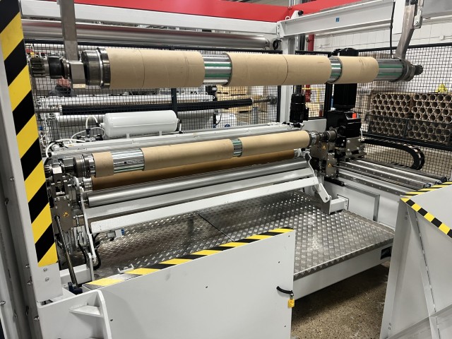
The Starlinger centerWINDER technology provides a semi-automatic roll change, by using two alternately working winding stations, in which one unit is in operation, and the other one is in standby with the prepared adhesive taped winding cores. After cross-cutting of the sheet under full line speed (no sheet accumulator necessary) the new reel-step starts automatically on the second winding unit. The finished sheet roll is transported out with a fully automatic handling system and is placed on a prepared pallet.
After having the finished roll placed, the handling system is retrieving the new prepared winding shaft (with adhesive taped core) in order to hand it over to the standby winding unit.
Components
- 2 independently motorized winding shafts
- Crosscutting device with transport roller
- Handling mechanism to lift finished roll to the pallet and load empty core
- Winding shafts put into change-over position with motors
- Speed feedback
- Meter counter
- Switchboard cabinet
- 2 pneumatic differential winding shafts:
- pneumatic winding shaft 6”
Technical data:
- Roll width: 2000 mm
- Possible sheet thickness:
- 860 µm (single roll)
- 200 – 1200 µm (double roll)
- 200 – 1000 µm (multiple roll)
- operating speed: 75 m/min
- 6” Max. winding diameter: (depending on width)
- 1100 mm
- 1100 mm multiple rolls (≥7mm gap)
- winding diameter: (dependent on ouput)
- cycle time 5 min for roll change One man handling
Additionally, the centerWINDER is equipped with an automated roll manipulation system in order to avoid a manually loading and unloading of the winding shafts.
This system provides a one-man operation due to the fact that the winding shaft remains inside the winding unit. The finished winded sheet roll is handed over from the winder to the one-man roll manipulator, and subsequently the roll can be wrapped before it will be placed on a pallet.
The operator manipulates the finished roll out of the winder by using a simple lift truck, or other similar systems, while the winding shaft remains connected with the roll manipulator.
The operator can now change the winding shaft with new winding cores, which can be wrapped with an adhesive tape easily in a semi-automatic mode.
Item 7. Quality control
Item 7.1. Inline viscosimeter iVON
For the inline iV measurement of the actual iV during the extrusion process with two melt pumps and a differential pressure measurement. The unit operates without losses and the measured material will be pumped back into melt stream of extruder.
Technical data:
- Main pump drive: 0,37 kW servo AC drive
- Pressure sensor: 2
-
Item 8. viscoLYZER
A wide range of parameters such as set points and process values of temperatures, pressures,
outputs and product parameters are stored in a file database with a default rate of two records per second.
An integrated visualisation service allows easy access to the stored data via standard web browser.
The MDP database is a powerful tool for QS management for documentation according to GMP (good manufacturing practice), process development in the field of material mixtures or product improvements, production management for the improvement of uptimes as well as predictive maintenance.
Hardware:
- Industrial grade PC with, Win10 Embedded, mounted inside the electrical cabinets,
- 16 GB RAM, Core i3 CPU, 32GB CFast for System
- 1 TB HDD for stored records Software:
- PLC configuration for recorded parameters
- Communication with B&R PLCs
- Fetching service for data collection
- Data access over rest API for external data use
- Visualisation service for Data viewing on HTML basis with a standard web browser
The internal Hard drive can store approx. 5 years of data based on 1000 recorded parameters/second.